1.Description
You can set a RGB controller using default values (mix, max values) with this module, and then start the controller. Changing external parameters is only possible in the inactive state.
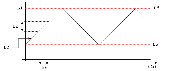
1.1.Sketch for explaining the manual parameters
 |
|
When setting the manual parameters, the entered data is checked for plausibility, and in the case of an error, error messages are output at Output 5 via14-byte text. In order to set the manual parameters for the respective colour, the operating mode (Input 7) should be set to 0. The controller for the corresponding colour must not be active (Inputs 1-3). The optimal sequence when setting the manual parameters is as follows:
- Max. limit value
- Min. limit value
- Default brightness can be set optionally
- The cycle duration
- The brightness change per cycle
- Select specification of start direction (value = 1, parameter brightness change per cycle is negated during start -> brightness is reduced at first after the start
- If necessary, all the set values can be reset via the Input reset
- Start of automatic function
2.Inputs
| No. | Name | Initialisation | Description |
|---|---|---|---|
| 1 | Start/Stop Red | 0 | On/Off colour red (1 = automatic function active, 0=setting of manual parameters) |
| 2 | Start/Stop Blue | 0 | On/Off colour blue (1 = automatic function active, 0=setting of manual parameters) |
| 3 | Start/Stop Green | 0 | On/Off colour green (1 = automatic function active, 0=setting of manual parameters) |
| 4 | Duration - Cycle (in sec.) Red | 0 | Cycle duration colour red (values > 0) |
| 5 | Duration - Cycle (in sec.) Blue | 0 | Cycle duration colour blue (values > 0) |
| 6 | Duration - Cycle (in sec.) Green | 0 | Cycle duration colour green (values > 0) |
| 7 | Selector switch (Manual parameter=0, Modes=1-6) | 0 | Operating mode selection (1 byte)�= 0 Setting the manual parameters and control of the colours via manual parameters. Operating mode selection (1 byte)�> 0 Optional call of finished mode by means of additional module RGB sequencer. Note To call finished mode, the additional module RGB�sequencer requires - 10005_RGB_Sequence_1.hsl! Without this module, the RGB universal sequencer can only be operated via the manual parameters - (Input 7 = 0). |
| 8 | Default brightness R | 0 | Default brightness colour red (Values <= max. Grenzwert und >= min. limit value) |
| 9 | Default brightness B | 0 | Default brightness colour blue (Values <=max. Grenzwert und >= min. limit value) |
| 10 | Default brightness G | 0 | Default brightness colour green (Values <=max. Grenzwert und >= min. limit value) |
| 11 | Reset colour R | 0 | Reset all parameters colour red |
| 12 | Reset colour B | 0 | Reset all parameters colour blue |
| 13 | Reset colour G | 0 | Reset all parameters colour green |
| 14 | Limit max. Brightness R | 0 | Max. limit value colour red (value < 255 und > 0) |
| 15 | Limit min. Brightness R | 0 | Min. limit value colour red (value < max. Grenzwert und >=0) |
| 16 | Limit max. Brightness B | 0 | Max. limit value colour blue (value < 255 und > 0) |
| 17 | Limit min. Brightness B | 0 | Min. limit value colour blue (value < max. Grenzwert und >=0) |
| 18 | Limit max. Brightness G | 0 | Max. limit value colour green (value < 255 und > 0) |
| 19 | Limit min. Brightness G | 0 | Min. limit value colour green (value < max. Grenzwert und >=0) |
| 20 | Specification of the start direction R | 0 | Specification of the start direction colour red (1 = the 1st brightness change per cycle is negated at the start (Input 23 *(-1), 0 = The start brightness change per cycle is not changed |
| 21 | Specification of the start direction B | 0 | Specification of the start direction colour blue (1 = the 1st brightness change per cycle is negated at the start (Input 24 *(-1), 0 = The start brightness change per cycle is not changed |
| 22 | Specification of the start direction G | 0 | Specification of the start direction colour green (1 = the 1st brightness change per cycle is negated at the start (Input 25 *(-1), 0 = The start brightness change per cycle is not changed |
| 23 | Brightness change per cycle Red | 0 | Brightness change per cycle colour red 0 <= Wert < (max. – min. Grenzwert)iv> |
| 24 | Brightness change per cycle Blue | 0 | Brightness change per cycle colour blue 0 <= Wert < (max. – min. Grenzwert)iv> |
| 25 | Brightness change per cycle Green | 0 | Brightness change per cycle colour green 0 <= Wert < (max. – min. Grenzwert)iv> |
3.Outputs
| No. | Name | Initialisation | SBC | Description |
|---|---|---|---|---|
| 1 | Output Value R | 0 | s | Output colour red |
| 2 | Output Value B | 0 | s | Output colour blue |
| 3 | Output Value G | 0 | s | Output colour green |
| 4 | Output Value 1-6 for modes | 0 | s | Operating mode output (0 or Mode 1-6) Warning The output is only used in conjunction with the module RGB sequencer! |
| 5 | Fault output (14-byte text) | "" | s | Fault output as 14-byte text in the case of implausible setting of the manual parameters |
s = send, sbc = send by change
4.Other
| Recalculation during start: | No |
|---|---|
| Module is retentive: | Yes |
| Internal designation: | 19011 |
| Category: | DALI and lighting control |